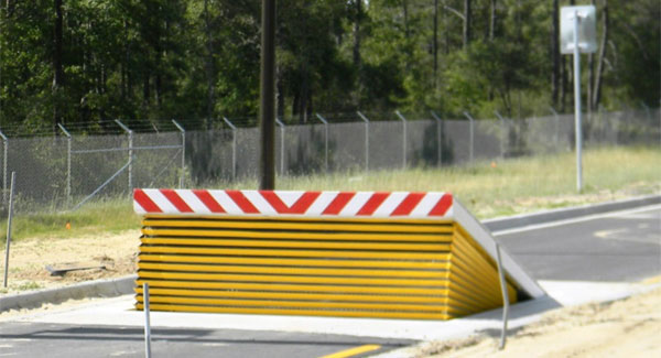
In the complying with discussion, reference is made to a surface of a foundation to which the wedge-style barrier is placed. In the illustrated embodiments, the top side of the anchor is considerably flush with the surface of the structure. In such personifications, the wedge-style obstacle might be placed straight to the surface area of the structure. In various other embodiments, the top side of the anchor may be somewhat increased over the surface area of the foundation or somewhat recessed listed below the surface of the structure. 1 is a front perspective view of a personification of a surface-mounted wedge-style barrier 10. As revealed, the obstacle 10 is placed to a surface area 12 of a foundation 14(e. g., a superficial foundation ). The structure
Wedge Barriers
14 and the surface 12 surface area which the barrier 10 is secured may safeguarded might from concrete. 2, the barrier 10 is mounted to or consists of an anchor or subframe (e. g., support 30 received FIG. 2 )safeguarded below the surface 12. For instance, the bather 10 may be bolted to the anchor or secured to the anchor by various other mechanical bolts. In the illustrated personification, the obstacle 10 consists of a wedge plate 16, that includes a part that is substantially identical with the surface 12 when the obstacle 10 is in the withdrawed setting. Simply put, lorries or individuals may pass over the barrier 10 when the barrier 10 remains in the pulled back setting and experience mild altitude about the surface 12 while on the barrier 10. As discussed carefully listed below, when the obstacle 10 remains in the released setting, the wedge plate 16 is held and supported in an elevated setting by a lifting system of the obstacle 10. In addition, the parts 18 may be bolted or otherwise mechanically paired to each other. In this way, repair work or substitute of several elements 18 may be streamlined and streamlined. That is, repair work or substitute of solitary elements
18 may be done quicker, conveniently, and price effectively. FIG. In certain embodiments, the support 30 might be a steel framework consisting of plates, beams(e. g., I-beams ), and/or other structures that are protected within the structure 14, which might be concrete. At the surface 12, a top side 28 of the my latest blog post support 30 might go to least partly revealed
, therefore enabling the accessory of the obstacle 10 to the anchor 30. g., threaded holes)in several beam of lights or plates of the anchor 30 might be revealed to the surface area 12. In this fashion, screws 32 or other mechanical fasteners may be utilized to secure the barrier 10 to the support 30. As the barrier 10 is mounted to the surface 12 of the structure 14, collection of particles and other material below the obstacle might be reduced, and parts of the bather 10 may not be revealed to below quality environments. As shown by reference numeral 52, the lifting mechanism 50 consists of parts disposed underneath the wedge plate 16. The elements 52 underneath the wedge plate 16 may include an electromechanical actuator, a camera, one or more web cam surfaces, and so forth. Furthermore, the lifting device 50 consists of a spring setting up 54
The springtime pole 58 is coupled to a cam(e. g., web cam 80 displayed in FIG. 4) of the training device 50. The springtimes 60 disposed concerning the springtime rod 58 are kept in compression by spring supports 62, consisting of a repaired spring assistance 64. click to investigate That is, the fixed spring assistance 64 is dealt with about the structure 14 et cetera click this of the bather 10.
Fascination About Wedge Barriers
g., springtime support 65 )may be repaired to completion of the springtime pole 58 to enable compression of the springs 60. As the springtimes 60 are compressed between the spring supports 62, the spring assembly 54 produces a force acting upon the web cam paired to the springtime pole 58 in a direction 66. The continuing to be pressure applied to
the cam webcam deploy release wedge plate 16 may might provided supplied an electromechanical actuator 84 or other actuator. The spring assembly 54 and the actuator 84(e. g., electromechanical actuator)might run with each other to equate the webcam and lift the wedge plate 16.
As discussed over, in the released placement, the wedge plate 16 serves to block access or travel past the obstacle 10. The barrier 10(e. g., the wedge plate 16 )might obstruct pedestrians or lorries from accessing a residential property or path. If a vehicle is traveling in the direction of the deployed wedge plate 16(e. For instance, in one situation, the security legs 86 may be expanded throughoutmaintenance of the barrier 10.